Host Interface Layer
In this page, we will explain how we design and implement host controller model, named Host Interface Layer - HIL.
HIL is consists of two components. First is host controller, which is interfaced to the host side. Second is SSD interface, which provides abstracted API to the host controller.
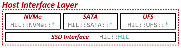
Components of Host Interface Layer
Host controller
In HIL, we implemented three host controller models - NVMe, SATA and UFS. Open-Channel SSD, which overrides NVMe, inherits NVMe.
Non-Volatile Memory Express
Non-volatile Memory Express - NVMe - is emerging standard for modern SSDs. Its first standard - NVMHCI - was released at 2011.
In SimpleSSD, we implemented NVMe interface based on NVMe Base Specification Revision 1.2.1, and update to NVMe Base Specification Revision 1.3c is in progress.
Following figure shows how each components are connected.
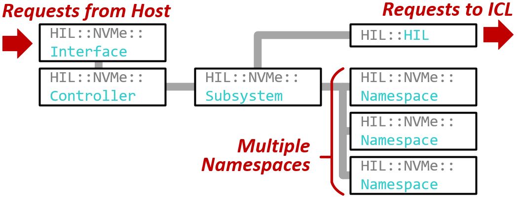
Components of NVMe model
Host interface
A SimpleSSD::HIL::NVMe::Interface abstract class defined in hil/nvme/interface.hh provides common API to simulators.
You can check NVMeInterface class defined in src/dev/storage/nvme_interface.hh of SimpleSSD-FullSystem and SIL::NVMe::Driver class defined in sil/nvme/nvme.hh of SimpleSSD-Standalone to know how they inherits the class.
Let’s see SimpleSSD::HIL::NVMe::Interface and SimpleSSD::DMAInterface which is parent class.
41 class DMAInterface {
42  public:
43   DMAInterface() {}
44   virtual ~DMAInterface() {}
45
46   virtual void dmaRead(uint64_t, uint64_t, uint8_t *, DMAFunction &,
47                        void * = nullptr) = 0;
48   virtual void dmaWrite(uint64_t, uint64_t, uint8_t *, DMAFunction &,
49                         void * = nullptr) = 0;
50 };
37 class Interface : public SimpleSSD::DMAInterface {
38  protected:
39   Controller *pController;
40
41  public:
42   virtual void updateInterrupt(uint16_t, bool) = 0;
43   virtual void getVendorID(uint16_t &, uint16_t &) = 0;
44 };
Two functions defined in DMAInterface are for Direct Memory Access, which is used when read/write data from/to system memory.
The updateInterrupt function will send interrupt at specified interrupt vector to the host.
The getVendorID function exists for Identify Controller NVMe command, because it requires vendor Id and subsystem vendor ID.
Other controller protocols implemented in SimpleSSD has similar interface definition.
Controller and Firmware
We designed NVMe controller/firmware in three components - Controller, Subsystem and Namespace. Controller handles all queue operations - read request from SQ, write response to CQ and send interrupt. Subsystem handles all NVMe admin commands, manages Namespaces and issues I/O to underlying SSD interface. Namespace handles all NVMe I/O (NVM) commands.
Controller
NVMe Controller, which handles all queue operations, is defined as SimpleSSD::HIL::NVMe::Controller in hil/nvme/controller.hh.
Following figure shows how Controller works.
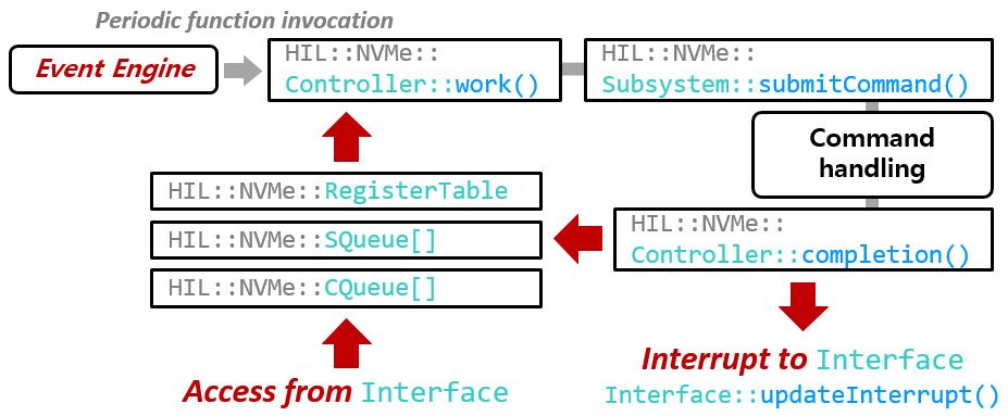
Controller operation diagram
An Event Engine will invoke Controller::work function periodically.
This period can be configured by WorkPeriod configuration parameter.
The Controller::work function will collect all submission queues using configured arbitration method (Controller::collectSQueue function).
New requests are inserted to internal FIFO queue (Controller::lSQFIFO variable).
If we have new request(s), Controller::handleRequest function called.
This function will invoke AbstractSubsystem::submitRequest function.
After AbstractSubsystem handled the request, it calls Controller::submit function to submit completion to internal FIFO queue (Controller::lCQFIFO variable).
Controller::submit function schedule event which calls Controller::completion function.
Controller::completion function will fill CQ entry and post interrupt through Controller::updateInterrupt function.
Controller::updateInterrupt function just calls Interface::updateInterrupt.
Subsystem
NVMe Subsystem, which handles admin commands, is defined as SimpleSSD::HIL::NVMe::Subsystem in hil/nvme/subsystem.hh.
Open-channel SSD Subsystem is defined as SimpleSSD::HIL::NVMe::OpenChannelSSD in hil/nvme/ocssd.hh.
Both subsystem inherits SimpleSSD::HIL::NVMe::AbstractSubsystem in hil/nvme/abstract_subsystem.hh.
We will only explain NVMe Subsystem, because Open-Channel SSD Subsystem only has minor changes to NVMe subsystem. Following figure shows how Subsystem works.
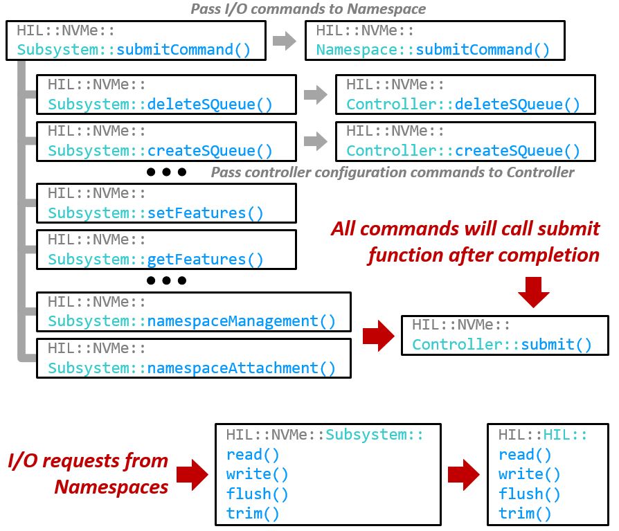
Subsystem operation diagram
NVMe Subsystem has two parts, first is command handling, second is I/O request handling. As Subsystem is able to have multiple namespaces, Subsystem should pass I/O requests from Namespaces to SSD interface of HIL.
Each NVMe command passed through Subsystem::submitCommand function is routed to specific Namespace if command is I/O command.
If arrived command is admin command, submitCommand function will check OPCODE and call proper function.
All commands invoke Controller::submit function to submit completion.
When I/O specific functions (Subsystem::read, write, flush and trim) called, these function will translate I/O unit and invoke functions in SSD interface (HIL::HIL::read, write, flush and trim).
By splitting linear logical space of SSD, Subsystem can maintain multiple Namespaces.
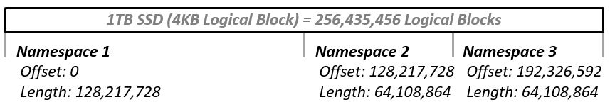
Namespace management diagram
Let’s assume there is 1TB SSD which uses 4K logical block. We can allocate three Namespaces, which has 512GB, 256GB and 256GB capacity, respectively. Subsystem will allocate Namespaces by finding offset and length. Subsystem searches unallocated spaces which can fit allocating Namespace (first-fit). If no such space, allocation will be failed.
Each Namespace has offset and length. This value will be used when translating I/O unit for SSD interface.
Namespace
NVMe Namespace, which handles I/O commands, is defined as SimpleSSD::HIL::NVMe::Namespace in hil/nvme/namespace.hh.
It has similar structure with NVMe Subsystem (both are handling commands).
When I/O command arrived, Namespace invokes corresponding function on Subsystem (read, write, flush and trim).
Serial AT Attachment
Serial AT Attachment - SATA - is conventional interface for SSDs and HDDs.
In SimpleSSD, we implemented SATA HBA based on Serial ATA Advanced host Controller Interface (AHCI) 1.3.1 and SATA PHY and protocol based on Serial ATA Revision 3.0.
Following figure shows how each components are connected.
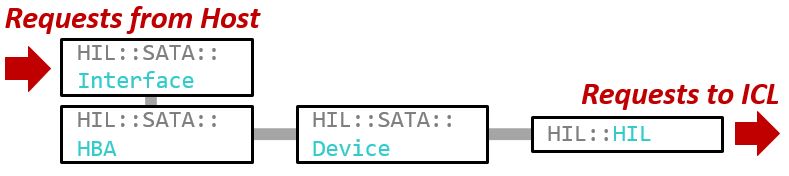
Components of SATA model
Host interface
A SimpleSSD::HIL::SATA::Interface abstract class defined in hil/sata/interface.hh provides common API to simulators.
You can check SATAInterface class defined in src/dev/storage/sata_interface.hh of SimpleSSD-FullSystem to know how they inherits the class.
SimpleSSD::HIL::SATA::Interface only contains virtual void updateInterrupt(bool) = 0; for interrupt posting.
Host Bus Adapter
SATA needs host-side controller, which called Host Bus Adapter (HBA). Multiple vendors designs own HBA, but we used AHCI specification because it is available on public domain.
AHCI HBA is defined as SimpleSSD::HIL::SATA::HBA in hil/sata/hba.hh.
We implemented only one port because only one SimpleSSD instance will connected to the HBA.
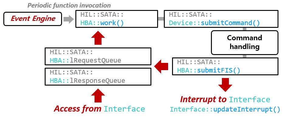
HBA operation diagram
Interface write AHCI registers (Generic Host Controller registers and Port registers) through HBA::writeAHCIRegister function.
Writing bits to PxCI register indicates corresponding NCQ has new request.
HBA will invoke HBA::processCommand function to enqueue request to internal FIFO (HBA::lRequestQueue).
As same as NVMe, Event Engine will periodically invoke HBA::work function.
This function will call HBA::handleRequest function and Device::submitCommand function will be called.
After command handling, Device calls HBA::submitFIS function to return response FIS to the host.
HBA::submitFIS function enqueue response to HBA::lResponseQueue and schedule event which calls HBA::handleResponse function.
handleResponse function will read first response from internal FIFO, write to NCQ and send interrupt using Interface::updateInterrupt function.
Device
Device, which connected to HBA, is defined as SimpleSSD::HIL::SATA::Device in hil/sata/device.hh.
Device can handle following ATA commands defined in ATA/ATAPI Command Set - 2 (ACS-2) and AT Attachment 8 - ATA/ATAPI Command Set (ATA8-ACS).
FLUSH CACHEFLUSH CACHE EXTIDENTIFY DEVICEREAD DMAREAD DMA EXTREAD FPDMA QUEUEDREAD SECTORREAD SECTOR EXTREAD VERIFY SECTORREAD VERIFY SECTOR EXTSET FEATUREWRITE DMAWRITE DMA EXTWRITE FPDMA QUEUEDWRITE SECTORWRITE SECTOR EXT
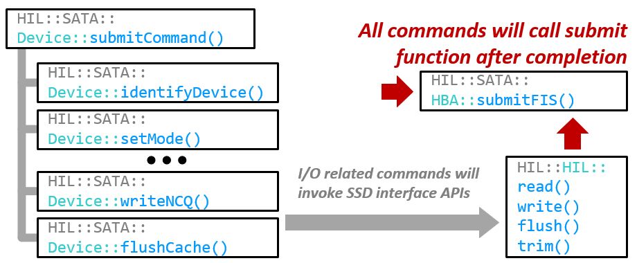
Device operation diagram
Device implementation is simple compared to NVMe Subsystem, because they don’t need to manage Namespace.
All commands passed through Device::submitCommand function will handled properly.
After completion, each command function will call HBA::submitFIS to report command result to the HBA.
I/O related commands READ*, WRITE* and FLUSH* will invoke functions of SSD interface (HIL::HIL::read, write and flush).
Universal Flash Storage
Universal Flash Storage - UFS - is interface designed for mobile storage. Most of smartphones uses UFS interfaces.
In SimpleSSD, we implemented UFS Host Controller Interface based on Universal Flash Storage (UFS) Host Controller Interface (JESD223), UFS PHY based on Specification for M-PHY Version 4.0 and UFS protocol based on Universal Flash Storage (UFS) Version 2.1 (JESD220C).
Implementation of UFS is very similar to SATA, as shown as following figure.
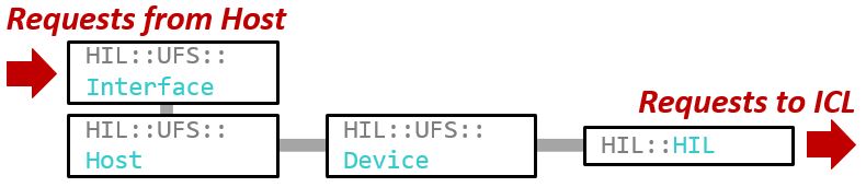
Components of SATA model
Host interface
A SimpleSSD::HIL::UFS::Interface abstract class defined in hil/ufs/interface.hh provides common API to simulators.
You can check UFSInterface class defined in src/dev/storage/ufs_interface.hh of SimpleSSD-FullSystem to know how they inherits the class.
SimpleSSD::HIL::UFS::Interface only contains two functions (generateInterrupt() and clearInterrupt()) for interrupt posting.
Host controller interface
Like SATA, UFS employs host controller named UFS Host Controller Interface - UFSHCI. This interface follows Universal Flash Storage (UFS) Host Controller Interface (JESD223) specification from JEDEC.
UFSHCI is defined as SimpleSSD::HIL::UFS::Host in hil/ufs/host.hh.
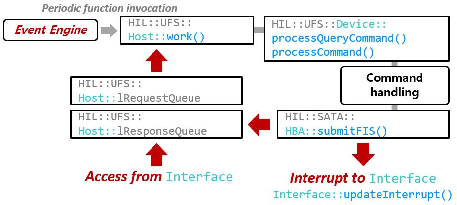
UFS Host Controller Interface operation diagram
Interface write UFSHCI registers through Host::writeRegister function.
UFS defines three types of commands:
UFS Transport Protocol Transfer (UTP Transfer)
UFS Transport Protocol Task Management (UTP Task)
UFS InterConnect Command (UIC Command)
Each command uses different doorbell for request arrival notification.
You can check REG_UTRLDBR for UTP Transfer, REG_UTMRLDBR for UTP Task and REG_UICCMDR for UIC Command.
As UTP Task is not implemented in UFS 2.1 and Linux Kernel, we did not implemented them in SimpleSSD. UIC Commands are only used when initializing UFS hardware - jobs such as boot up M-PHY link and so on. So we only implemented two mandatory commands.
As same as NVMe and SATA, Event Engine will periodically invoke Host::work function.
Host::handleRequest function is invoked by work and determine the request is valid.
Host::processUTPCommand parse the request and call proper handler for the request.
UFS Transfer defines three types of commands:
Command (SCSI protocol)
Native UFS Command
Device Management Command
Native UFS Command is not defined in UFS 2.1 specification. So we implemented Command and Device Management Command.
Device::processCommand function will handle Command and Device::processQueryCommand function will handle Device Management Command.
Completion routine also defined in handleRequest function.
See lambda functions named doRequest and doWrite.
doWrite function schedule completion routine (Host::completion).
completion function will send interrupt using Interface::updateInterrupt function.
Device
Device, which connected to UFSHCI, is defined as SimpleSSD::HIL::UFS::Device in hil/ufs/device.hh.
UFS used SCSI command sets for I/O (SCSI Block Commands - 3 (SBC-3) and SCSI Primary Commands - 4 (SPC-4)). Device can handle following SCSI commands.
INQUERYMODE SELECT 10MODE SENSE 10READ 6READ 10READ CAPACITY 10READ CAPACITY 16START STOP UNITTEST UNIT READYREPORT LUNSVERIFY 10WRITE 6WRITE 10SYNCHRONIZE CACHE 10
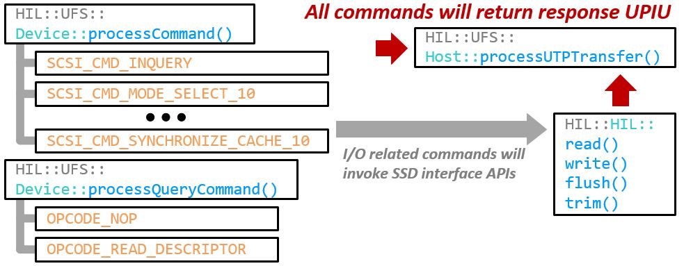
Device operation diagram
Device implementation is similar to SATA, but they have two command handling functions - processCommand and processQueryCommand.
After completion, each SCSI command function will call callback handler provided as parameter of processCommand function.
processQueryCommand will return results immediately.
I/O related commands READ*, WRITE* and SYNCHRONIZE CACHE will invoke functions of SSD interface (HIL::HIL::read, write and flush).
SSD interface
SSD interface of HIL is quite simple.
It is defined as SimpleSSD::HIL::HIL in hil/hil.hh.
It receives I/O request from host controllers, passing to Internal Cache Layer.